global@hmeonline.com
Mon to Fri 09:00 – 17:30


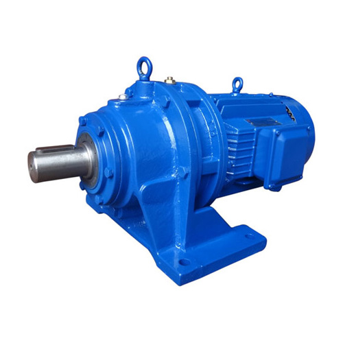
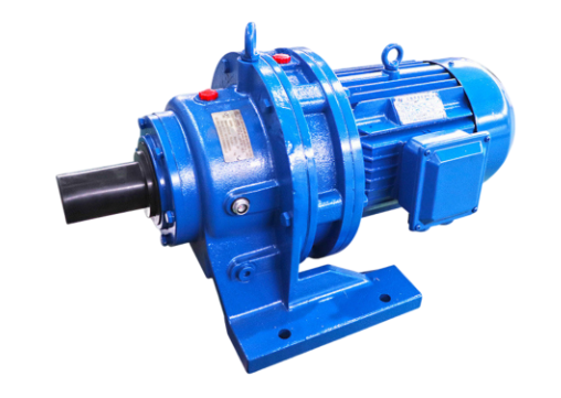
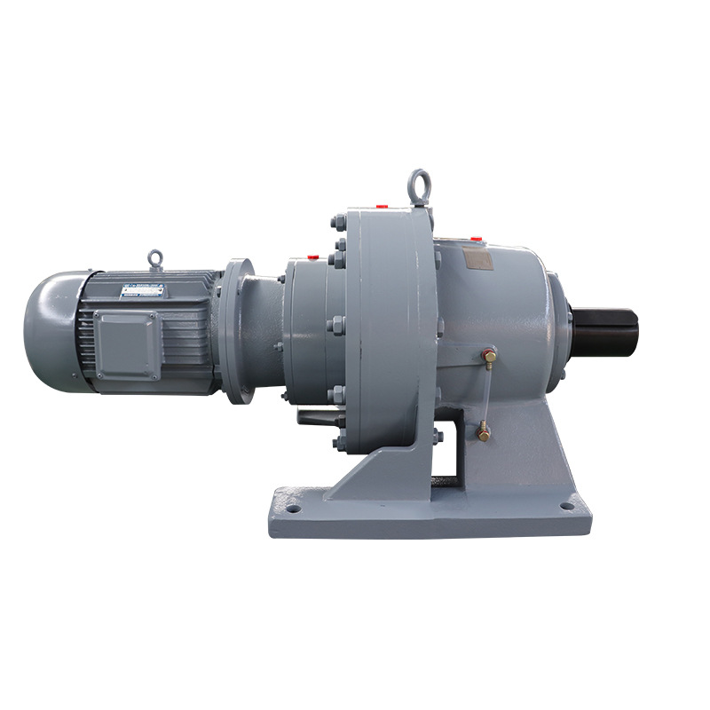
Cycloid pin gear reducer is a novel transmission device which applies the principle of planetary transmission and adopts cycloid pin tooth meshing. All transmission devices of cycloidal pinwheel reducer can be divided into three parts: input part, deceleration part and output part. The input shaft is equipped with a double eccentric sleeve with an offset of 180 °, and the eccentric sleeve is equipped with two roller bearings called the rotating arm to form the H mechanism. The center holes of the two cycloid wheels are the raceway of the rotating arm bearing on the eccentric sleeve, and the cycloid wheel is meshed with a group of annular needle teeth on the needle gear to form an internal meshing reduction mechanism with a tooth difference of one tooth.
Feature
1. The reducer is suitable for the 24-hour continuous working system, and allows for positive and backward operation.
2. The output shaft steering of the primary drive reducer is opposite to the input shaft steering, and the output shaft steering of the secondary transmission reducer is the same as the input shaft steering.
3. The reducer has no self-locking function.If used for dangerous situations such as the lifting device, select the brake motor or add the prepared moving device to the input end.
4. The output shaft of the reducer cannot withstand the axial force.
5. Overload protection device shall be installed when the overload phenomenon may occur.
6. The foot reducer should be installed on a level without vibration and very solid level.The inclination of the reducer shaft line shall not be greater than ± 15°.
7. When the reducer is working in bad working conditions, frequent start and stop, and high temperature or low temperature occasions, please contact the technical department of our company.
8. The input shaft and output shaft of the reducer are cylindrical and connected with ordinary flat keys.Normal flat key size is as specified in GB1096.
9. When the reducer joins the coupling for supporting machinery, the coaxial degree of the two axial lines shall not exceed the range permitted by the coupling.
10. When the reducer is coupled with the gear and the sprocket, the parallel degree of the two axial lines must be guaranteed.
11. When using sprockets for transmission, do not overloose the tooth chain, otherwise there will be an impact force when starting. The shell material is recommended to be changed to ductile iron to strengthen the shell strength.
12. When connecting the coupling, gear, sprocket and other couplings to the output shaft of the reducer, the direct hammer method shall not be used. Use the shaft extension screw hole into the bolt and press it through the pressure plate.
13. The installed reducer must be tested before formal use.With normal empty load operation, then gradually loading and operation.