global@hmeonline.com
Mon to Fri 09:00 – 17:30


System Introduction
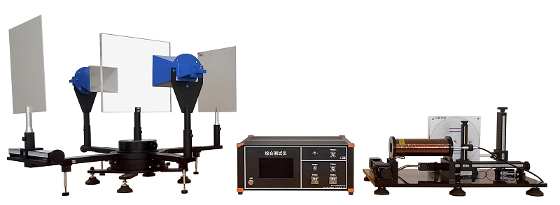
Electromagnetic wave transmission is categorized into wireless and wired transmission, with wired transmission primarily divided into waveguide and coaxial cable transmission. Waveguide transmission offers the advantages of low transmission loss and high power handling, but is complex to fabricate and primarily used as feeder lines for high-power receiving antennas. Coaxial cable transmission is simple to fabricate and inexpensive, but suffers from high power handling limitations. This experimental system primarily studies the transmission characteristics of electromagnetic waves in waveguides. Waveguide transmission utilizes the most widely used three-centimeter waveguide. The signal source utilizes digital phase-locked loop technology, offering high stability, low noise figure, and high power. It is equipped with a frequency-selective amplifier, power meter, measurement cables, and nine standard waveguide accessories, enabling the completion of a variety of waveguide experiments.
System Features
1. Multifunctional digital phase-locked loop signal source: It can meet the experimental requirements of waveguides. It also has a digital LCD screen that displays the frequency and power of the output signal and can adjust the signal parameters.
2. Contains a variety of waveguide accessories, which can be used with waveguide measurement cables to complete various waveguide transmission experiments.
3. Waveguide frequency meter: adopts absorption resonant cavity, with high Q value, good feel and high accuracy.
4. Waveguide variable attenuator: adopts spiral adjustment method, can directly read the attenuation value, reliable and convenient.
Experimental content
Experiment 1: System Adjustment and Frequency Check
Experiment 2: S-curve small standing wave ratio measurement
Experiment 3: Standing Wave Measurement
Experiment 4: Power Measurement Application
Experiment 5: Attenuation Measurement
Experiment 6: Use of Eh Impedance Adapter
Experiment 7: Pyramidal Antenna Measurement
Experiment 8: Directional Coupler Performance Measurement
Experiment 9: Impedance Measurement
Experiment 10: Two-port network S-parameter measurement
Experiment 11: Measurement of λg (waveguide wavelength) and its relationship with λo (air wavelength)
Specification