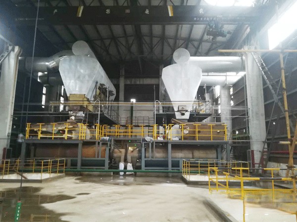
Anhydrous calcium chloride granulator
Anhydrous calcium chloride granulation line
1.2 Introduction to fluidized bed spray granulation process:
1) Technical requirements:
40% calcium chloride solution is sprayed into the fluidized bed of the granulator, and the finished product is ≥ 94% calcium chloride particles. Product status: spherical, diameter 2~4mm, product material temperature: 60 ℃.
2) Process gas flow
The system blower blows the natural air into the customized natural gas heating furnace of the calcium chloride system and mixes it with the high-temperature flue gas for heating. After that, the high-temperature air is blown into the air inlet assembly and the air equalizer of the granulation system. It is divided into numerous average fine high-temperature air flows and blown into the spray granulation fluidized bed under pressure. It is mixed with the calcium chloride solution injected by the feed pump and the crystal seeds in the fluidized bed for heat and mass transfer, completing the coating granulation process and drying the calcium chloride particles to no water, After drying, the system tail gas carries some calcium powder and enters the spray tower to increase the solution concentration by about 3%. The tail gas then enters the induced draft fan of the system and is transported to the on-site water bath dust collector to spray alkali liquor. The flue gas and the system tail gas are discharged uniformly, and the tail gas is discharged into the atmosphere after meeting the environmental protection requirements.
1.3 Mechanism of spray coating granulation process:
The material preparation solution is sprayed into the fluidized-bed granulator in the form of atomization. The atomized droplets directly contact the material layer (crystal core layer) with intense fluidization. The droplets adhere to the surface of the crystal core before removing the moisture, forming a local wetting layer. At the same time, the relatively fine powder layer is adhered to the local wetting layer, and the moisture of the local wetting layer is gradually removed. The powder layer and the droplet layer form a layer of substances adhered to the surface of the crystal core due to the moisture removal, The nucleus particles are increased, and this process is repeated. In the fluidized-bed granulation area, the crystal nucleus continuously receives the adhesion of atomized droplets, and the impact between the crystal nuclei plus the gradual removal of water. Therefore, the increase of particles is gradual, layered and uniform, and the evaporation of water is also synchronous; Therefore, this method of granulation provides a uniform and dense structure and improves the strength of particles. The granulation mechanism is mostly coating accumulation granulation, and a small part is agglomeration granulation.
1.4 Materials and characteristics of granulation system
1.4.1 The key components of the granulator that contact with liquid: spray gun, connecting rod and nozzle are made of 316L.
The connection design of the spray gun and the granulator body adopts the quick-opening mode to facilitate the removal of the spray gun and the replacement of the spray head. The spray gun is designed with an anti-blocking structure, and the preventive design prevents the blockage of the spray head from affecting the long-term stability.
1.4.2 The dust remover is a two-stage wet dust remover. The first stage is a waste heat recovery spray tower. The concentrated calcium liquid is returned to the inside of the granulator. The second stage is a water bath dust remover. The equipment structure is a special submerged structure.
1.4.3 The gas hot blast furnace adopts the latest fully automatic energy-saving combustion technology. The gas furnace equipment features that the furnace liner is made of 310S heat-resistant stainless steel, and the furnace body is completely insulated with aluminum silicate fiber cotton; Electrical characteristics: the combustion system is controlled by PLC fully automatic proportional adjustment, and the combustion head is equipped with anti-return air structure; It also has built-in Honeywell flame detection device (ultraviolet type, not ordinary thermal type). If the combustion process suddenly flameout and the flame cannot be detected by flame detection, the gas source will be directly cut off to ensure the full safe operation environment on site; The pneumatic cut-off butterfly valve is one for operation and one for standby; This combustion air supply process system is completely different from all combustion schemes in the city. The heat source module saves more than 40% of the power than the general combustion high temperature relay air supply process; The specific data are as follows: the general negative pressure combustion is that the fan draws 450 ℃ high temperature air at negative pressure, the air density will decrease with the increase of temperature, and the volume proportion will expand. The density at 20 ℃ at normal temperature is 1.2, and the density at 400 ℃ at high temperature is 0.5. It can be seen that the air volume flow of the high-efficiency energy-saving combustion system is far less than that of the ordinary negative pressure combustion system; Avoid selecting high power, high temperature resistance and high material for the fan; The comparison shows the absolute advantages of high-efficiency energy-saving combustion system.