- Agriculture / Food
- Apparel / Textiles / Accessories
- Auto / Transportation
- Bags / Shoes / Accessories
- Electronics
- Electrical Equipment / Components / Telecoms
- Gifts / Sports / Toys
- Health / Beauty
- Home / Lights / Construction
- Machinery / Industrial Parts / Tools
- Metallurgy / Chemicals / Rubber / Plastics
- Packaging / Advertising / Office
University laboratory teaching instruments
-
5G Microwave Communication System and Antenna Virtual Simulation Design Platform
Platform Overview
This design platform is mainly aimed at the experimental teaching and course design of "Microwave Technology", "Microwave Circuits", "Antenna Principles" and other courses offered by microwave communication engineering, electronic engineering, communication engineering and other majors in various universities, and is the latest product developed for graduation projects.
Platform Features
1. The system adopts a whole-board external design, consisting of fully open cavity-free circuit units; the whole system has no coaxial cable connection, and the signal direction is controlled by switches, replacing the modular plug-in cable method.
2. The system utilizes mainstream 5G communication frequency bands and consists of a digital baseband modem unit, a 5G RF transceiver unit, a microwave integrated test platform, and a microwave antenna remote teaching virtual simulation platform. The 5G RF transceiver unit utilizes microwave high-frequency boards, and the open display circuits include: intermediate frequency filters, mixers, broadband power splitters, broadband power amplifiers, dual-branch couplers, various microstrip filters, DDS frequency synthesizers, and digital audio and video acquisition modules.
3. The platform has a built-in 10.1-inch LCD screen and supports keyboard and mouse operation. It also supports wireless remote connection and file transmission, an extended USB interface for mouse connection and file copying and installation, 2 serial ports for data transmission, a built-in LAN port, and an HDMI interface to support connection with projection equipment for demonstration and teaching, and supports high-definition image and voice acquisition and display.
4. Built-in RF point frequency and broadband sweep frequency signal source, sweep frequency bandwidth and point frequency output can be set.
Experimental content
Experiment 1: Testing of Microwave High-Pass Filters
Experiment 2: Testing of Microwave Low-Pass Filters
Experiment 3: Testing of Microwave Couplers
Experiment 4: Testing of Microwave Phase-Locked Signal Source
Experiment 5: Testing a Microwave Voltage Controlled Oscillator (VCO)
Experiment 6: Testing of Microwave Bandpass Filters
Experiment 7: Testing of Microwave Band-Rejection Filters
Experiment 8: Testing the IF AGC Amplifier
Experiment 9: Microwave Amplifier Design and Measurement
Experiment 10: Testing of Microwave Power Splitter
Experiment 11: Testing of Microwave Electrically Adjustable Attenuator
Experiment 12: Testing of Microwave Mixers
Experiment 13: Microwave Duplex Communication Experiment
Experiment 14: Microwave Relay Communication Experiment
Experiment 15: Microwave Relay Communication Experiment
Experiment 16: Reflection coefficient and standing wave ratio test of coaxial cable
Experiment 17: Characteristic Test of Microstrip Transmission Line
Experiment 18: Debugging and testing the upconverter
Experiment 19: Debugging and testing the downconverter
Experiment 20: Introduction to Microwave Open Platform Simulation Software (ADS)
Experiment 21: Secondary Development of Microwave Open Platform Transmission System
Experiment 22: Secondary Development of Microwave Open Platform Receiving System
Experiment 23: Secondary Development of Microwave Low-Noise Amplifiers -
Waveguide measurement experimental platform
System Introduction
Electromagnetic wave transmission is categorized into wireless and wired transmission, with wired transmission primarily divided into waveguide and coaxial cable transmission. Waveguide transmission offers the advantages of low transmission loss and high power handling, but is complex to fabricate and primarily used as feeder lines for high-power receiving antennas. Coaxial cable transmission is simple to fabricate and inexpensive, but suffers from high power handling limitations. This experimental system primarily studies the transmission characteristics of electromagnetic waves in waveguides. Waveguide transmission utilizes the most widely used three-centimeter waveguide. The signal source utilizes digital phase-locked loop technology, offering high stability, low noise figure, and high power. It is equipped with a frequency-selective amplifier, power meter, measurement cables, and nine standard waveguide accessories, enabling the completion of a variety of waveguide experiments.
System Features
1. Multifunctional digital phase-locked loop signal source: It can meet the experimental requirements of waveguides. It also has a digital LCD screen that displays the frequency and power of the output signal and can adjust the signal parameters.
2. Contains a variety of waveguide accessories, which can be used with waveguide measurement cables to complete various waveguide transmission experiments.
3. Waveguide frequency meter: adopts absorption resonant cavity, with high Q value, good feel and high accuracy.
4. Waveguide variable attenuator: adopts spiral adjustment method, can directly read the attenuation value, reliable and convenient.
Experimental content
Experiment 1: System Adjustment and Frequency Check
Experiment 2: S-curve small standing wave ratio measurement
Experiment 3: Standing Wave Measurement
Experiment 4: Power Measurement Application
Experiment 5: Attenuation Measurement
Experiment 6: Use of Eh Impedance Adapter
Experiment 7: Pyramidal Antenna Measurement
Experiment 8: Directional Coupler Performance Measurement
Experiment 9: Impedance Measurement
Experiment 10: Two-port network S-parameter measurement
Experiment 11: Measurement of λg (waveguide wavelength) and its relationship with λo (air wavelength) -
Antenna Measurement Training System Platform
System Introduction
As a carrier for transmitting or receiving electromagnetic waves in radio equipment, antennas play a very important role in engineering systems such as radio communications, broadcasting, television, radar, navigation, electronic countermeasures, and remote sensing.
This experimental system is mainly aimed at experimental courses in electronic information majors such as communication engineering, electromagnetic field and microwave technology, and antenna technology in colleges and universities. It is designed for experimental teaching, course design, graduation design, and secondary development.
System Features
1. The transmitting system features a built-in touchscreen LCD screen. Touch keys select the signal frequency band output and have a function to shut down the transmitting signal. The touch keys have power attenuation capabilities, allowing you to adjust the signal output power by touch. A reset function switches the transmitting power back to its initial value. The LCD screen displays the transmitting frequency and power level. The transmitting platform has a built-in power amplifier module to meet different testing requirements. The receiving system has a built-in touchscreen LCD screen that enables automated control of the antenna turntable's forward and reverse rotation, speed control, adjustable angle rotation, and sector sweep. The receiving system also has a built-in power test module that supports automatic and manual testing and drawing of directional patterns. It also has built-in USB and RS232 interfaces for connecting to a computer to display the antenna directional pattern and a printer to print the directional pattern.
2. The system includes software for automatically drawing antenna patterns, which are displayed directly on the LCD interface. It has the function of switching between straight coordinates and polar coordinates, and can measure the characteristics of various antennas. The test data can be saved or exported.
3. Antenna turntable: Equipped with an antenna pitch adjustment device, it can measure the vertical receiving radiation characteristics of the antenna; the vertical rotation platform can measure various antenna polarization patterns;
4. The built-in vector network analyzer supports simultaneous measurement of S11 and S21 in one scan, measurement of S parameters, voltage standing wave ratio, impedance, transmission line length, transmission line loss, Smith chart, and completes and quantitatively tests parameters such as the directivity pattern, antenna gain, antenna frequency response, antenna input impedance, and other parameters of different antennas, as well as extended experiments such as antenna matching network design.
Experimental content
Experiment 1: Testing the Directivity Pattern of Logarithmic Periodic Antennas
Experiment 2: Testing the Directional Pattern of the Yagi Antenna
Experiment 3: Testing the Parabolic Antenna Pattern
Experiment 4: Homemade Yagi Antenna and Radiation Pattern Testing
Experiment 5: Omnidirectional Antenna Pattern Test
Experiment 6: Horn Antenna Directional Pattern Test
Experiment 7: Testing the Gain of Logarithmic Periodic Antennas
Experiment 8: Test of Yagi antenna gain
Experiment 9: Testing the Gain of Parabolic Antennas
Experiment 10: Gain test of homemade Yagi antenna
Experiment 11: Testing the Polarization of Parabolic Antennas
Experiment 12: Circularly Polarized Antenna Axis Ratio Test
Experiment 13: Log-Periodic Antenna Standing Wave Ratio and Impedance Test
Experiment 14: Yagi Antenna Standing Wave Ratio and Impedance Test
Experiment 15: Parabolic Antenna Standing Wave Ratio and Impedance Test
Experiment 16: Helical Antenna Standing Wave Ratio Test and Impedance Test
Experiment 17: Smith Chart Test -
Electromagnetic wave experimental platform
Platform Introduction
The electromagnetic field, electromagnetic wave and antenna technology experiment is an essential experimental course for electronic information engineering, electromagnetic field and electromagnetic wave, microwave technology and antenna technology majors in various universities.
This experimental platform is mainly designed for experimental teaching, course design, graduation design, and secondary development of electromagnetic fields, microwave technology and other majors in colleges and universities.
Platform Features
1. 10.1-inch LCD screen: Windows operating system; the platform adopts screw adjustment + LCD digital display to convert rotary motion into linear motion, bidirectional adjustment device; at the same time, digital online display, synchronous tracking and measurement of displacement distance
2. The system integrates master control software that supports parameter measurement, parameter adjustment, antenna pattern testing, coaxial line testing, and vector network testing. It also supports loading the Internet + remote teaching and training management platform, electromagnetic wave characteristics virtual simulation software, and antenna darkroom virtual simulation platform.
3. Five-axis antenna measurement rotation platform: It can realize multiple antenna reception modes such as up and down azimuth - pitch - multi-polarization reception - X-shift, etc.; at the same time, it can convert quantitative values into dynamic graphical images for intuitive display.
4. Vector network analyzer: supports simultaneous measurement of S11 and S21 in one scan, measurement of S parameters, voltage standing wave ratio, impedance, transmission line length, transmission line loss, and Smith chart.
Experimental content
Experiment 1: Simulation mapping experiment of electrostatic field
Experiment 2: Verification of Maxwell's Electromagnetic Field Theory
Experiment 3: Receiver Antenna Production Experiment
Experiment 4: Electromagnetic Wave Interference Operation Experiment
Experiment 5: Testing and Calculation of Displacement Current
Experiment 6: Experiment on the operation of virtual polarization characteristics of electromagnetic waves
Experiment 7: Antenna Receiver Pitch Measurement Experiment
Experiment 8: Antenna Receiver Multi-Polarization Measurement Experiment
Experiment 9: Testing of Electromagnetic Wave Nodes, Amplitude, and Standing Waves
Experiment 11: Testing the wavelength of electromagnetic waves
Experiment 12: Electromagnetic wave virtual reflection operation experiment
Experiment 13: Frequency Test of Electromagnetic Waves
Experiment 14: Power Test of Electromagnetic Waves
Experiment 15: Single Slit Diffraction Experiment (Optional)
Experiment 16: Double-slit diffraction experiment (optional)
Experiment 17: PIN Modulation Characteristics of Electromagnetic Waves
Experiment 18: Antenna Gain Test
Experiment 19: Antenna Pattern Testing
Experiment 20: The size of the electrical signal induced by the antenna at a certain point in space -
Comprehensive experimental device for testing electromagnetic wave transmission characteristics
Product Overview
This platform is suitable for university physics courses in electromagnetism and electrostatics. It also has a unique "Internet + online teaching" model, which can realize remote online electromagnetic wave characteristics simulation experiment content; at the same time, it is equipped with an Internet + remote teaching experiment management platform to realize online video teaching, teaching management, online assessment, grade correction and other functions.
Features
1. Comprehensiveness: It integrates a variety of instruments and meters, improves the stability of equipment use, students' hands-on operation, and ensures students' safety; it is also convenient for laboratory management and storage; and it allows students to conduct simulation experiments on the platform;
2. Flexibility: The experimental components are humanized in design, the experimental range has horizontal and vertical displacement functions, manual rotation adjustment, and the range distance is digitally readable;
3. Operability: The experimental input and output interfaces are designed on the front end of the device. Before doing each experiment, students follow the detailed steps in the provided instruction manual to ensure the smoothness and safety of the experiment.
4. Visibility: Built-in 10-inch LCD screen: supports opening experimental simulation software for simulation learning, and also supports keyboard and mouse operation, wireless remote connection and file transmission; the LCD screen has an extended USB interface for mouse connection file copy and installation, and 2 serial ports for data transmission; built-in LAN port and HDMI interface support network teaching or projection equipment connection demonstration teaching.
5. Internet + Experimental Simulation: It can realize Internet distance learning, solve the problem of online teaching due to environmental factors; at the same time, it can allow students to see the experimental phenomena more intuitively and vividly, deepen students' strong interest in professional courses, and also adjust parameters to observe different experimental results and phenomena for easy analysis and understanding;
Experimental content
Experiment 1: Electromagnetic wave reflection experiment
Experiment 2: Electromagnetic Wave Interference Experiment
Experiment 3: Electromagnetic wave refraction measurement experiment
Experiment 4: Single-slit diffraction of electromagnetic waves
Experiment 5: Double-slit diffraction of electromagnetic waves
Experiment 6: Polarization and Polarization of Electromagnetic Waves
Experiment 7: Antenna Pattern Testing
Experiment 8: Parameter Measurement of Uniform Lossless Media -
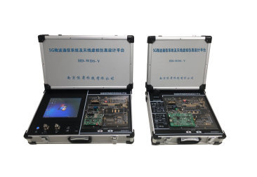
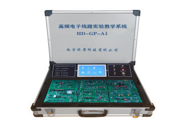
Radio high-frequency electronic circuit experimental system
Product Introduction
The upgraded high-frequency electronic circuit experiment system integrates basic experimental teaching and digital development modules. It is carefully designed according to the requirements of the teaching syllabus and the needs of e-sports competitions. It adopts functions such as human-computer interaction, digital signal source, digital frequency meter, analog circuit, digital development circuit, etc. In addition to conducting individual experiments in each module, the modules can also be combined into some comprehensive experiments such as wireless voice FM and AM transceiver systems.
Features
1. The experimental platform adopts touch operation of human-computer interaction interface, and integrates digital dual-channel signal output, optional waveform type, frequency counting display, experimental guidance consultation and other functions; the platform adopts modular experimental unit, configures secondary development modules for completion design, and can be composed of (frequency modulation, amplitude modulation) transceiver system to build communication.
2. The human-computer interaction interface uses a 7-inch touch LCD display: it contains functions such as equipment introduction, signal source selection, frequency counting, experimental project review, power management, etc.
3. The waveforms include sine wave, square wave, pulse wave (duty cycle is adjustable, pulse width and cycle time are accurately adjustable), triangle wave, partial sine wave, CMOS wave, DC level, half wave, full wave, Sinker pulse and other waveforms.
4. The digital development module contains digital phase-locked loop, programmable attenuator, programmable amplifier, digital sound source and other modules, which can help with e-sports competitions and graduation project development programming.
Experimental content
Experiment 1: Small Signal Tuned (Single and Double Tuned) Amplifier Experiment
Experiment 2: Integrated frequency-selective amplifier experiment
Experiment 3: Diode Double-Balanced Mixer Experiment
Experiment 4: Analog Multiplier Mixing Experiment
Experiment 5: Three-point sine wave oscillator (LC, crystal) experiment
Experiment 6: Voltage-controlled Oscillator Experiment
Experiment 7: Nonlinear Class C Power Amplifier Experiment
Experiment 8: Linear Broadband Power Amplifier Experiment
Experiment 9: Collector Amplitude Modulation Experiment
Experiment 10: Analog Multiplier Amplitude Modulation Experiment
Experiment 11: Envelope Detection and Synchronous Detection Experiment
Experiment 12: Varactor Diode Frequency Modulation Experiment
Experiment 13: Orthogonal Frequency Demodulation and Phase-Locked Frequency Demodulation Experiment
Experiment 14: Simulated Phase-Locked Loop Experiment
Experiment 15: Automatic Gain Control (AGC) Experiment
Experiment 16: Testing the Phase-Locked Loop Local Oscillator
Experiment 17: Testing the Digital Attenuator
Experiment 18: Gain Controllable Digital Power Amplifier Test
Experiment 19: Digital Audio Source Modulation Signal Test -
High frequency electronic circuit experimental teaching system
Product Introduction
The high-frequency electronic circuit experiment system is meticulously designed based on the syllabus requirements and the needs of experimental teaching. The entire system adopts a modular design approach, with circuits connected by switches (reducing wiring). While each module can be used for independent experiments, they can also be connected to form comprehensive experiments such as wireless voice transceiver systems. The experimental system comes with a built-in high-frequency signal source, frequency counter, and music signal generator. Simply plug in the corresponding experimental templates and complete all experiments without the need for other instruments (besides an oscilloscope).
Features
1. The unit modular design allows users to select modules according to their needs, which can save money and facilitate future upgrades.
2. The system has its own DDS signal generator: it can generate a variety of waveforms such as sine wave, square wave, triangle wave, pulse wave, and arbitrary wave, and has the functions of duty cycle adjustment, frequency sweep, frequency measurement signal frequency and counter, etc.
3. Use TFT color display: can simultaneously display output signal waveform, amplitude, frequency, etc.
4. Multiple waveform types: sine wave, square wave, pulse wave (duty cycle adjustable, pulse width and cycle time accurately adjustable), triangle wave, partial sine wave, CMOS wave, DC level, half wave, full wave, Sinker pulse and other waveforms.
5. Circuit stability and reliability: Various unit circuits have easily consumable components, and the system is designed to be self-maintained and replaceable, which can quickly improve teaching quality.
Experimental courses can be offered
Experiment 1: Small Signal Tuned (Single and Double Tuned) Amplifier Experiment
Experiment 2: Integrated frequency-selective amplifier experiment
Experiment 3: Diode Double-Balanced Mixer Experiment
Experiment 4: Analog Multiplier Mixing Experiment
Experiment 5: Three-point sine wave oscillator (LC, crystal) experiment
Experiment 6: Voltage-controlled Oscillator Experiment
Experiment 7: Nonlinear Class C Power Amplifier Experiment
Experiment 8: Linear Broadband Power Amplifier Experiment
Experiment 9: Collector Amplitude Modulation Experiment
Experiment 10: Analog Multiplier Amplitude Modulation Experiment
Experiment 11: Envelope Detection and Synchronous Detection Experiment
Experiment 12: Varactor Diode Frequency Modulation Experiment
Experiment 13: Orthogonal Frequency Demodulation and Phase-Locked Frequency Demodulation Experiment
Experiment 14: Simulated Phase-Locked Loop Experiment
Experiment 15: Automatic Gain Control (AGC) Experiment
Experiment 16: Phase-locked frequency synthesizer assembly and debugging experiment -
Simulation Circuit Experiment Teaching System
Product Overview
The new generation of analog circuit experiment boxes integrates analog circuit experimental units, high-quality signal generators, and specialized analog signal measurement instruments into a single box, creating a functionally integrated advanced experimental environment for users and bringing about innovative changes in the teaching and experimental model of analog circuits. By integrating new measurement and analysis methods with the experimental platform, the teaching experiment content is more comprehensive and complete, and the equipment is more durable, easy to maintain, and easy to operate, enhancing student learning and experimental effectiveness. It can also significantly reduce the demand for laboratory space, providing optimal experimental equipment for schools to establish high-end analog circuit laboratories.
Features
1. The system utilizes an advanced, integrated structure, combining analog circuit design and experimental units, signal generators, and specialized analog signal measurement instruments. This significantly improves student experimental efficiency and enhances their innovative design, problem analysis, and problem-solving abilities. The experimental platform utilizes a baseboard and modular design for ease of use, upgrades, and maintenance, ensuring equipment reliability and stability.
2. Utilizing a novel circuit construction method, the system's experimental units provide the key components for constructing simulated experimental circuits. Students can quickly construct experimental circuits by selecting and switching short-circuiting blocks and connecting a small number of wires. Some circuits also allow for convenient integration of new components, making circuit construction flexible and efficient while also fostering the development of students' design, analysis, and synthesis skills.
3. The system uses a high-quality voltage-stabilized power supply with excellent performance in resisting short circuits and overcurrent, avoiding possible damage during the experiment and making the system reliable and safe.
4. The experimental platform provides the signal source (built-in) required for the experiment with a rich variety of signal source waveforms. It also has a built-in frequency display function that can measure the signal source frequency with intuitive readings; and a built-in voltmeter that can measure positive and negative voltages.
5. All experimental modules on the experimental platform utilize standard silkscreen printing, along with schematics and symbols, to facilitate students' understanding of circuit composition and operating principles. The platform's operability and adjustment components utilize high-quality, hand-twist potentiometers, which are both durable and easy to operate. The platform's power and signal output ports utilize locking jacks, allowing for wire leads. A breadboard is also provided, allowing students to build their own circuits based on the experimental content. This approach fosters innovative thinking and hands-on skills.
Experimental courses can be offered
Experiment 1: Single-stage amplifier circuit
Experiment 2: Two-stage amplifier circuit
Experiment 3: Negative Feedback Amplifier Circuit
Experiment 4: Emitter Follower
Experiment 5: Differential Amplifier Circuit
Experiment 6: Proportional Sum Operation Circuit
Experiment 7: Integral and Differential Circuits
Experiment 8: Waveform Generator Circuit
Experiment 9: Voltage Comparator
Experiment 10: IC Circuit RC Sine Wave Oscillator
Experiment 11: Integrated Power Amplifier
Experiment 12: Transistor Power Amplifier Circuit
Experiment 13: Rectification, Filtering and Parallel Voltage Regulator Circuit
Experiment 14: Series Voltage Regulator Circuit
Experiment 15: Integrated Voltage Regulator
Experiment 16: LC Oscillator
Experiment 17: Complementary Symmetrical Power Amplifier -
Digital Circuit Experiment Teaching System
Product Overview
The experimental box is closely linked to the teaching syllabus of courses such as "Basics of Digital Electronic Technology" in colleges and universities. It has rich experimental content and can fully meet the experimental teaching needs of digital circuit courses in electrical majors in various colleges and universities.
Features
1. The modular design facilitates later replacement and maintenance. Module content can also be customized individually, allowing users to choose according to their own teaching practices.
Component symbols are printed on the front of the experimental board, and the components are arranged on the back of the circuit board, with reserved component interfaces. The potentiometers are all hand-twist with screws for easy operation. The power and signal output ports use locking jacks for wire lead-out. The power supply unit has an indicator light and an independent power supply area, which is safer and more reliable, and convenient for connecting the experimental box.
3. There are simulation examples of various experimental circuits. Students can design circuits or make physical circuits based on the simulation examples, providing a platform for secondary development.
Experimental courses can be offered
Experiment 1: Logic Pen Experiment and Analysis
Experiment 2: Op amp circuit
Experiment 3: Gate circuit logic function experiment
Experiment 4: Testing of Commonly Used Combinatorial Logic Function Devices
Experiment 5: Half adder, full adder and logic operation experiment
Experiment 6: Four-way priority decision circuit
Experiment 7: Functional Test of RS Trigger
Experiment 8: JK and D flip-flop logic functions and main parameter tests
Experiment 9: Tri-state output flip-flop and latch
Experiment 10: Asynchronous Binary Counter Experiment
Experiment 11: Synchronous Binary Counter Experiment
Experiment 12: Functional Test of Shift Register
Experiment 13: Counting, decoding, and display circuit experiments
Experiment 14: 555 integrated circuit and its application
Experiment 15: Waveform Generation and Monostable Trigger
Experiment 16: Design of Sequence Detector
Experiment 17: D/A Digital-to-Analog Converter
Experiment 18: A/D Analog-to-Digital Converter
Experiment 19: AVR secondary development experiment -
Experimental Teaching System for Communication Principles
Product Introduction
The course "Principles of Communications" is one of the most important professional foundation courses in the fields of communications, electronics, and information. The experimental platform can be used as a teaching platform for communication engineering, electronic information, computer communications, etc. in colleges and universities. It focuses on the generation, transmission, and demodulation technologies and testing methods of various communication signals in communication systems, so that students can quickly master and become familiar with the basic theories and concepts of communication systems .
Features
1. Adopting modern open design concept, it integrates verification experiment and autonomous experiment, and the secondary development experiment function is more powerful and more adaptable to user requirements.
2. It comes with analog signal source and clock/digital signal source, built-in power supply +5V, +12V, -12V, no external power supply is required.
3. The comprehensive experimental functions between the experimental box modules are powerful. A single experimental box can realize simplex communication; two experimental boxes can realize duplex communication. At the same time, it can also complete networking and various signal optical fiber transmission and module digital exchange experiments between optical fibers and program-controlled switches.
4. The experimental box is equipped with communication E1 interface, 2M interface, and RS232 interface, which can complete communication experiments between PC and experimental system.
Experimental courses can be offered
Experiment 1: Amplitude Shift Keying (ASK) Modulation and Demodulation Experiment
Experiment 2: Analog Modulation and Demodulation: AM, Single Sideband (SSB), Double Sideband (DSB)
Experiment 3: Analog Modulation and Demodulation: FM
Experiment 4: Channel Simulation Experiment: White Noise Experiment
Experiment 5: Testing the waveforms of various analog signals
Experiment 6: Measuring the Waveform of a Tone Signal
Experiment 7: Familiarize yourself with the waveforms of each measurement point of the CPLD programmable signal generator
Experiment 8: Measure and analyze the waveforms and data at each measurement point
Experiment 9: Learning the programming operation of CPLD programmable devices
Experiment 10: Communication channel terminal sending experiment
Experiment 11: Communication Channel Terminal Receiver Filter Experiment
Experiment 12: Sampling Theorem Experiment
Experiment 13: 555 clock generator experiment
Experiment 14: Pulse Amplitude Modulation (PAM) and System Experiment
Experiment 15: Incremental Modulation CVSD (M) Encoding Experiment
Experiment 16: Comparison of M encoding and decoding when the working clock is variable
Experiment 17: Observing A-Law PCM 8-bit Encoding Using a Synchronous Simple Signal
Experiment 18: Pulse Code Modulation (PCM) and System Experiment
Experiment 19: PCM coding time division multiplexing timing analysis experiment
Experiment 20: Basic Phase-Locked Loop Experiment
Experiment 21: Bandwidth measurement of synchronous belt and catch belt
Experiment 22: Phase-locked digital frequency synthesizer experiment
Experiment 23: Two-phase BPSK modulation and demodulation experiment
Experiment 24: PSK demodulation carrier extraction experiment
Experiment 25: Bit Timing and Bit Synchronization Extraction Experiment
Experiment 26: Signal Code Regeneration Experiment
Experiment 27: Eye Diagram Observation and Analysis Experiment
Experiment 28: Simulated Eye Diagram Observation and Measurement Experiment
Experiment 29: Frequency Shift Keying (FSK) Modulation Experiment
Experiment 30: AMI/HDB3 code conversion coding observation experiment
Experiment 31: Ideal Channel Simulation Experiment
Experiment 32: Bit Error Rate Test of PSK Channel
Experiment 33: Channel Error Test
Experiment 34: Comprehensive Experiment on Speech Signals and Communication System Principles
Experiment 35: Single Experiment Box to Implement Simplex Communication System Experiment
Experiment 36: Two experimental boxes realize duplex communication system experiment


